An FTTH Cable Production line is an integrated set of modules that converts optical fiber into completed drop and distribution cable products with consistent, repeatable quality.
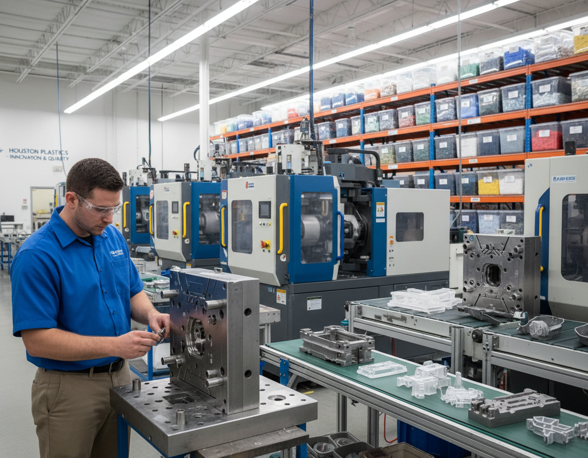
Fiber Secondary Coating Line
This introduction guides plant managers, process engineers, sourcing teams, and students in the United States who review how industrial production equipment shapes fine fiber into rugged cable assemblies for service and communication networks.
Fundamentally, the full-chain objective is straightforward: shield the fiber, maintain low optical loss, build in installation strength, and ship an output that holds up to indoor and outdoor conditions.
Top-tier equipment delivers reliable tension regulation, synchronized motion control, standardized process windows, and clear documentation for customer sign-off. This article helps pair the right line configuration, materials, and test plan to the target product instead of ordering equipment first and backfilling requirements afterward.
Readers will trace steps such as fiber preparation, buffering/coating, fiber organization and stranding, strength member integration, sheathing (outer-jacket extrusion), optional armor, and end-of-line testing and packaging.
Key takeaways: A properly specified line minimizes defects and supports predictable delivery. Align the process before buying machines to save time and cost.
How A Fiber Optic Cable Production Line Operates Today
Where last-mile drop and distribution demands meet factory practice.
Modern production lines convert fine glass fiber into finished products used in United States broadband buildouts. Last-mile drop cable and FTTH drop demand drives high volumes, so manufacturers focus on repeatable handling methods and standards compliance.
Core Modules And Material Flow
Material follows a clear sequence: pay-off → guiding/tensioning → secondary coating/color application → organization / SZ stranding → strength member feed → jacketing and sheathing → cooling/curing → take-up and testing.
Modules → Outcomes
Consistent fiber handling reduces attenuation and protects signal integrity for data and communications. Consistent jacketing helps installation and connector preparation. Inline monitoring flags loss events before reels leave the line.
- Indoor vs. outdoor use: different jacket compounds and buffering needs.
- Armored variants add steel tape or wire for rodent and crush resistance.
- Drop designs favor tight-buffered fibers and simplified connector prep.
Buyers should treat lines as modular systems. Plants add armoring or skip steps to fit the product type. Throughput is limited by curing and dimensional control, not only motor speed.
Define Your Product & Data Standards Before Equipment Purchase
Begin with a clear product map that specifies the cable type, core count, intended service environment, and target user scenarios. That early definition narrows the modules your line must include, from tight-buffer units to SZ stranding and jacket extrusion equipment.
Select Standards And Measurable Targets
Select fiber standards such as ITU-T G.652D or bend-insensitive G.657A1/A2 based on bend requirements and routing constraints. Document optical loss budgets, tensile strength, crush and bend limits, and environmental durability before selecting vendors.
- Identify the precise product type and fiber/core count so you can define modules and control requirements.
- Define attenuation (loss) budgets and mechanical strength targets to guide material selection.
- Define required materials (buffer polymers, jacket compounds) and confirm supplier availability in the U.S.
Data Standards, Traceability & Validation
Translate targets into factory information: captured process variables, lot-level traceability, and customer-required acceptance test reports. Use R&D pilot runs to validate settings and cut scale-up time.
Fiber Ribbon Line
| Target | Factory Impact | Typical Action |
|---|---|---|
| Low loss | Control of tension and alignment | Inline attenuation checks |
| High strength | Strength-element selection | Integrate aramid or metal |
| Bend resistance | Choice of fiber type | Use G.657 variants |
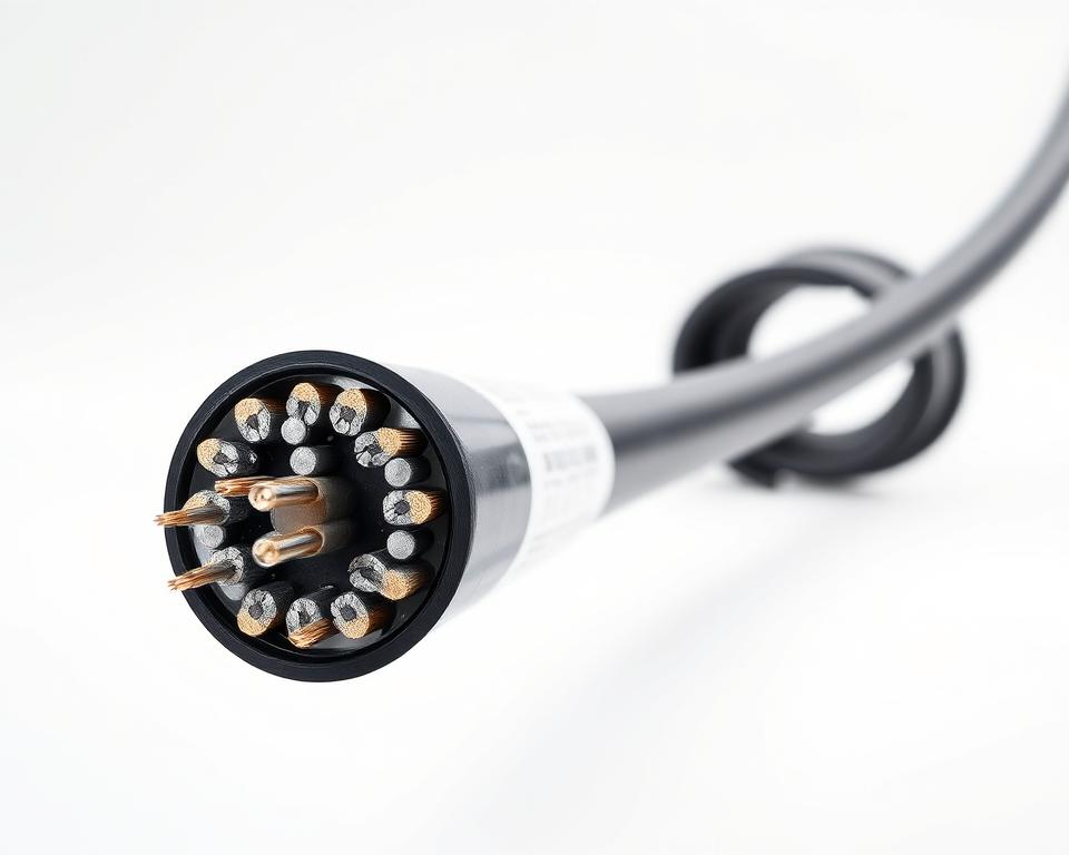
Build Quality Into The Optical Fiber: Core, Cladding & Coating Essentials
High-quality optical performance starts in the glass, where core purity and cladding design define the boundaries for loss.
Core and cladding create the central layer structure: an ultra-pure silica core carries the light while lower-index cladding keeps it confined. This geometry underpins low-loss transmission and stable optical behavior once cabled.
From Preform To Drawn Glass Fiber
Manufacturing begins with preform laydown and consolidation. Moisture removal via a high-temperature furnace cuts defects that increase attenuation.
The draw process pulls glass into a micron-scale strand. Geometry control at this stage links directly to steady attenuation and predictable transmission performance. A single blank can yield roughly 5 km of fiber, so stability saves time and cost.
Primary Coating And Color Coding
The primary coating protects against scratches and handling damage; it is not the main strength element. Color identification simplifies splicing, troubleshooting, and downstream fiber management.
- Preform consolidation: remove contaminants and moisture.
- Draw: manage diameter and tension for low attenuation.
- Coating and color: protect and identify each fiber.
| Layer Element | Function | Buyer check |
|---|---|---|
| Fiber core | Transmit light with minimal attenuation | Specify purity and loss specs |
| Cladding | Confine light, control modal behavior | Confirm refractive index profile and geometry |
| Primary coating | Scratch protection and color ID | Verify coating adhesion and color coding |
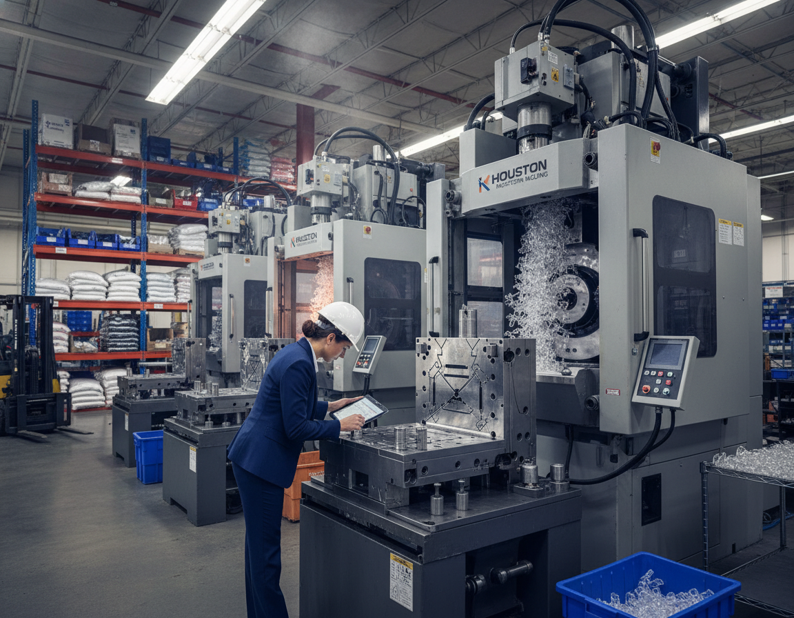
FTTH Cable Production: Step By Step Line Setup From Buffering To Sheathing
A practical line setup takes each fiber from pay-off through buffering, stranding, and the outer jacket to a finished reel.
Secondary coating and fiber coloring stations apply dual-layer, UV-cured coatings (≈250 µm) and one-to-twelve channel color coding for identification and traceability. Stable UV curing and web tension reduce mix-ups and rework.
Buffering And Materials
Tight buffering (600–900 µm) protects handling and simplifies connector preparation. Choice of Hytrel, PVC, or LSZH changes flexibility, temp range, and flame/smoke behavior.
SZ Stranding, Organization
SZ stranding uses an alternating lay to balance geometry and provide flexibility. Servo control for up to 24 fibers keeps lay pitch consistent and lowers attenuation risk.
Strength Members & Jacketing
Aramid yarn is the standard tensile element; it provides pull strength without stressing the fibers during installation.
Outer jacket extrusion using PVC, PE, or LSZH follows. Speeds often run 60–90 m/min and demand tight OD and concentricity control.
Armoring, Control Points
If crush or rodent resistance is needed, add steel tape or wire armor and control tension. Operators monitor tension, cure state, concentricity, OD, and cooling to maintain quality.
| Step | Primary Control | Typical Range |
|---|---|---|
| Secondary coating | UV cure plus tension | ≈250 µm, high curing consistency |
| Tight buffering | Material selection | 600–900 µm (Hytrel/PVC/LSZH) |
| Sheathing | OD and concentricity | 60–90 m/min |
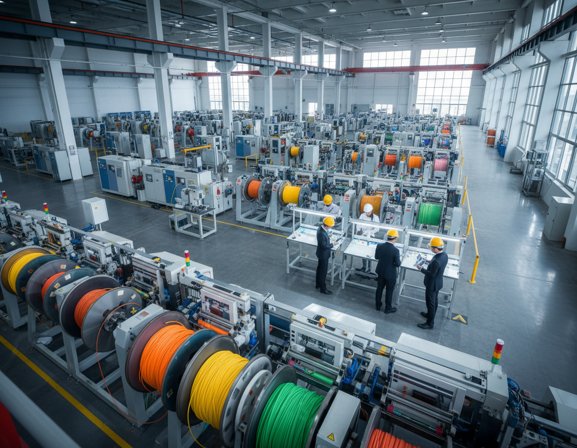
Optimize Production Speed And Process Control With Modern Automation
When factories run for 24/7 output, synchronized controls and tension systems become the backbone of reliable manufacturing.
PLC, HMI And Closed-Loop Tension For Steady Operation
Modern lines use Siemens PLC + HMI platforms to synchronize modules, manage recipes, and record process information. Closed-loop tension control protects fiber during start, stop, and speed changes.
Fiber Ribbone Line
Match Speed To Curing And Dimensional Control
Line speed often caps where curing, cooling, or extrusion dimensional control cannot keep up. UV cure completeness, water trough stability, and chill capacity set the true ceiling.
Layout, Changeover, Procurement
Layout affects uptime: correct pay-off/take-up placement and protected fiber paths reduce damage and speed changeovers.
- Design quick-change tooling and documented setup procedures to reduce changeover time.
- Specify industrial power (380 V AC ±10%) and a typical ≤55 kW load when ordering equipment.
- Require remote diagnostics, parts availability, and responsive service from the equipment company.
| Focus | Operational Value | Typical Goal |
|---|---|---|
| Synchronization | Lower scrap, repeatable runs | Siemens PLC/HMI |
| Closed-loop tension | Protects fiber; keeps loss stable | Closed-loop with high accuracy |
| Layout & changeover | Less downtime | Quick-change tooling, staging |
Testing And Quality Control To Reduce Loss And Improve Delivery Reliability
Robust testing and clear quality control turn raw fiber into reliable, field-ready cable reels.
Begin with optical verification. Inline attenuation testing and return loss checks confirm signal performance before reels exit the line.
Optical Checks And Signal Integrity
Attenuation testing is the primary guardrail against performance complaints. Higher loss readings often indicate handling damage, microbends, or contamination.
Return loss checks target reflections that can affect sensitive links and tight network margins.
Mechanical, Environmental Validation
- Tensile pull tests validate strength members and safe installation loads.
- Crush and bend tests mimic real-world stresses during installation.
- Temperature cycling, moisture soak, and vibration tests de-risk outdoor and aerial routes.
| Test | Objective | Typical Decision |
|---|---|---|
| Attenuation test | Measure attenuation per km | Pass/fail against specification |
| Mechanical validation | Validate pull, crush, and bend | Installation performance rating |
| Environmental tests | Recreate field conditions | Durability confirmation |
Traceability connects raw material lots, inline data, and final test results to reel IDs. Proper reeling, labeling, and protective packaging protect quality and accelerate customer acceptance and delivery.
Conclusion
A clear manufacturing plan ties product targets to the exact line modules and control limits needed for reliable output. Define the intended FTTH product, service environment, and measurable specs before selecting equipment or layout.
Fiber optic fundamentals — core, cladding, and coating — set the optic baseline. Careful handling upstream preserves data integrity and keeps end-product quality within acceptance limits.
Configure buffering, organization/stranding, strength members, and jacket choices to fit installation realities. Use automation and closed-loop controls to hold speed, cut scrap, and make delivery predictable in U.S. markets.
Operational discipline matters: implement comprehensive testing, reel-level traceability, and documented quality systems so customers can accept reels quickly. Next step: convert these points into a purchasing checklist (spec targets, utilities, layout, and acceptance tests) before requesting quotes or trials.
Related: Optimizing Efficiency With Automated Fiber Ribbon Line Systems